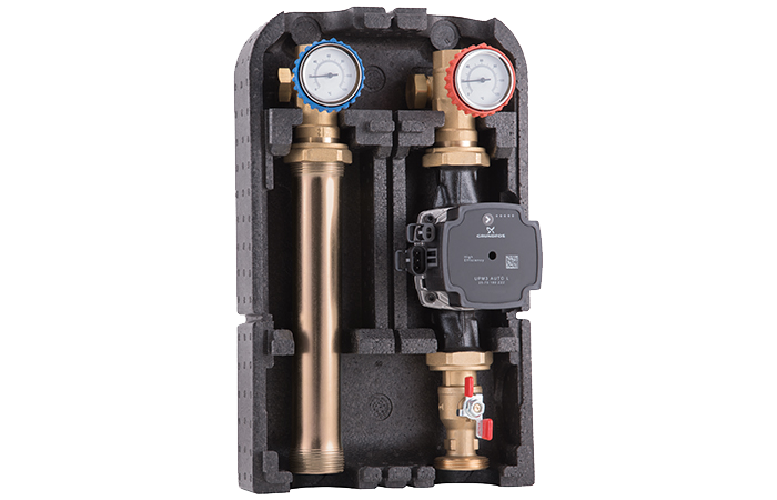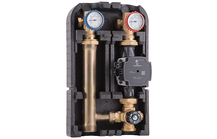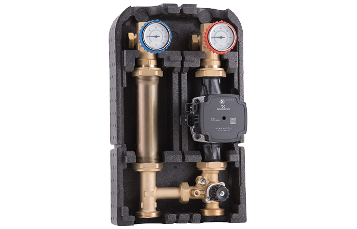
615


615
Differential by-pass valve 0,2–2,5 m w.g.
- Working temperature range: 0 (no frost)–90 °C
- Max working pressure: 10 bar
- Setting: - 615-615.1 series: 0,2–2,5 m w.g
- - 616-616.1-617.1-617.1.N series: 2–6,5 m w.g.
- Connection distance:
- - 615-616 series: 65 mm
- - 615.1-616.1-617.1-617.1.N series: 55 mm
- Suitable fluids: water for thermal systems, glycol solutions (max 50%)
- Threaded connections: ISO 228-1
- Product codes
- Description
- Documentation
- Accessories
- Alternative products
Product codes
| Item code | Size |
|
|
Download the 3D file |
|---|---|---|---|---|
| 615015000 | G 3/4 RN | 1 | 40 |
Description
In variable flow rate systems, managed by regulating valves (for example: thermostatic valves, thermo-electric actuators, zone valves), the modulation and closing of terminals lead to a decrease of the requested flow rate and, as a consequence, an increase of the head on the still open terminals.
The differential by-pass valve:
- limits, at the setting value, the differential pressure between the two installation points, allowing the pump to work closer to the design head conditions and higher efficiency zones;
- by-passes, towards the return, an excess flow rate amount which is proportional to the number of circuits in modulation or closing phase;
- avoids wear and noise (usually hisses and whistles) of the devices in modulation, caused by the speed increase of the fluid when passing through the regulating devices.
The differential by-pass valve can be installed for example across a pump, between the flow and return of a boiler circuit, at the basis or top of risers, between the flow and return of distribution and regulating groups, at the end of the distribution manifolds. The valve setting corresponds to the head losses of the most disadvantaged circuit downstream of the valve or, when installed close to the pump, to the pump design head. In order to by-pass high flow rate values, it’s possible to install several valves in parallel.
Documentation
Accessories
Alternative products


